
Most of the cold-surface complaints we are called out to look at have nothing to do with the glass. The rooflight itself is performing to specification and the problem is the 100 to 300mm of construction immediately around it, where the roof insulation was interrupted, the timber that replaced it conducts heat five times faster, and the plasterboard reveal ends up as the coldest surface in the room. That interruption is a thermal bridge. This page explains where the bridges form at a rooflight opening, what they cost in heat and in surface temperature, and how the detail gets built so they do not.
A thermal bridge, defined at an opening
A thermal bridge is any part of a construction where heat crosses more easily than through the surrounding build-up. It arises for two reasons: a material of higher conductivity replaces the insulation, or the geometry forces heat to converge on a smaller area of internal surface than it left on the external side.
An opening in a roof produces both at once. Structural timber replaces insulation at the trimmers. Insulation gets interrupted, compressed or omitted where access is awkward. And at the corners of the opening, heat flows from three directions into a single line of plasterboard.
The consequence is not primarily a heating bill. It is a band of cold surface where moisture in the room finds its first opportunity to condense, and where mould takes hold within a season or two if it stays wet.
The three bridges every roof opening creates
They form at different places and they are addressed by different means.
The first is the structural bridge: the trimmers and doubled rafters framing the opening, made of timber that conducts at about 0.13 W/mK against mineral wool at 0.035. That is a factor of nearly four, spread across the full depth of the roof and around the whole perimeter.
The second is the interface bridge: the gap between the timber and the rooflight frame, typically 10 to 20mm all round, which is where the packers and fixings live and where insulation is easiest to leave out.
The third is the geometric bridge at the reveal, where the internal surface area is smaller than the external and heat concentrates. This one exists even in a perfectly built detail and can only be reduced, never eliminated.
Timber, and the conductivity nobody accounts for
Softwood conducts at 0.12 to 0.14 W/mK. That is far better than steel and far worse than any insulation.
A standard rafter roof already loses noticeably more heat than the insulation figure suggests, because timber occupies perhaps 12 per cent of the plane. Around an opening, that fraction rises sharply. A trimmed opening has doubled rafters both sides and a trimmer top and bottom, which can put continuous timber around the entire perimeter at 100mm or 150mm wide.
Nothing removes that timber, because it is holding the roof up. What can be done is to reduce its effect: insulate over it where the build-up allows, insulate outboard of it in a warm roof, and never treat the timber face as the place the insulation stops. A 25mm layer of rigid insulation carried across the trimmer face is one of the cheapest interventions available at that stage of the job and one of the most commonly skipped.
Where the insulation stops, and why it stops early
Insulation almost always stops short of the frame, and the reason is practical rather than negligent.
The rooflight is fitted first, weathered in and made secure, because the roof is never left open overnight. The insulation goes in afterwards, from below, by somebody working overhead with a knife and a headtorch, reaching into a 15mm gap between a timber trimmer and an aluminium-clad frame.
What happens next is predictable. The last 30mm is difficult, the light is poor, and a fibrous batt is easier to stuff than to fit. Either a void is left or the material is compressed to a fraction of its thickness, and compressed mineral wool loses much of its performance because the still air it relies on has been squeezed out.
The fix is sequencing and material choice: cut rigid board to fit the actual measured gap in two pieces rather than forcing one, or use an expanding insulating foam rated for the application in gaps under 20mm where a board cannot be cut accurately. Both take a few minutes per side and both are decided before the plasterboard goes near it.
The flat-roof upstand as a heat path
On a flat roof, the rooflight sits on an upstand or kerb, usually 150mm high, which lifts the frame clear of standing water and gives the covering somewhere to terminate.
That upstand is a wall of timber or a proprietary insulated kerb standing proud of the insulation plane, exposed on three faces to outside air and connected at its base directly to the warm side of the roof. Thermally it behaves like a fin, drawing heat out of the deck and dissipating it into the wind.
An uninsulated timber upstand can lose more heat per metre of perimeter than the glazing loses per square metre. On a 1200mm by 1200mm unit that is 4.8 metres of fin around a 1.44 square metre aperture, and it is entirely invisible once the covering is on.
Insulating an upstand: inside, outside, or both
Three approaches and they are not equivalent.
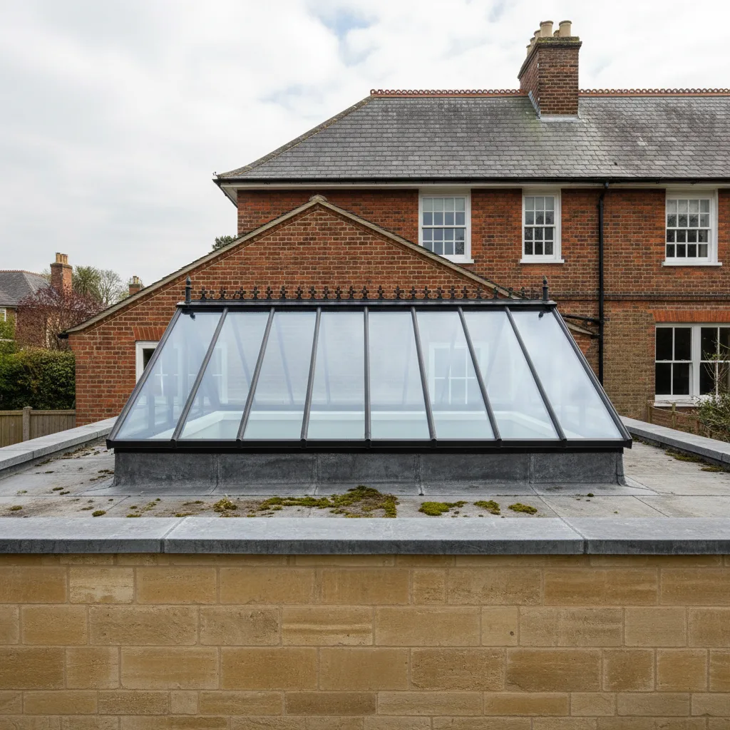
Insulating internally, by lining the inside face of the kerb, is the easiest and the least effective. The timber remains outboard of the insulation and still conducts heat from the warm deck up and out.
Insulating externally, by wrapping the outside of the kerb in rigid board before the covering is dressed up it, keeps the timber on the warm side and works properly. It also raises the finished upstand dimension, so the unit has to be ordered to suit and the covering has to be dressed over a slightly larger box.
A proprietary insulated kerb, built as a composite with the insulation within the wall of the kerb itself, does the same job with the dimensions already resolved. It costs more than site-made timber and it removes an entire category of error. On a warm-roof extension we generally specify one.
The reveal, and the surface temperature at its foot
The reveal is the plastered return between the ceiling and the rooflight frame, and it is the surface where the whole detail gets its report card.
Where the perimeter is properly insulated, the reveal runs within two or three degrees of the ceiling, no water forms on it, and paint stays sound. Where the perimeter is bridged, the reveal at its junction with the frame can sit five to eight degrees below room temperature. That is beneath the dew point of ordinary occupied air, so it wets, and because the reveal is the point everything drains towards, it wets first and dries last.
A splayed reveal helps in two ways. It bounces more daylight into the room, and it presents a larger internal surface for the same heat flow, so the surface temperature at any point is higher. Splaying the lower reveal on a pitched roof and both side reveals on a flat one is the version worth building.
Psi values at the perimeter, and the numbers involved
The heat lost along a junction is a linear thermal transmittance in W/mK, and published values exist for standard rooflight details.
A well-insulated rooflight perimeter sits around 0.04 to 0.06 W/mK. A poorly detailed one with insulation stopped short of the frame can reach 0.25 or higher. On a 1200mm by 1200mm unit with 4.8 metres of perimeter, that gap is nearly one watt per degree, meaning the badly built perimeter loses more than the entire 1.44 square metres of triple glazing above it.
That comparison is the point of this page. The glazing upgrade is a line on an invoice. The perimeter detail is a half hour of care that costs nothing and is worth more.
Condensation and mould as the visible symptom
The bridge itself is invisible. The symptom is a dark line following the reveal, usually worst at the lower corners on a pitched unit and along the shaded side on a flat one.
The sequence is always the same. The surface runs cold, moisture forms on it overnight, it dries partially during the day, and the cycle repeats. Within a winter or two the emulsion loses its bond and mould colonises. Owners wipe it, repaint it and watch it come back, and reasonably conclude the rooflight is admitting water.
The way to tell the difference matters. Water from outside appears after rain, follows the run of the roof, and stains outward from a specific point. Water from a cold surface appears on cold still nights regardless of rain, forms evenly along a line, and is worst in the rooms with the highest humidity. If it happens on a dry frosty morning, it is a thermal bridge.
Compressed insulation and the performance it loses
Mineral wool works because it traps still air. Compress a 100mm batt into a 50mm gap and you have not doubled its density to advantage, you have squeezed out the air it was working with.

The effective conductivity rises, and beyond a certain compression the material approaches the performance of the fibre itself rather than the assembly. As a rule, a batt compressed below about 70 per cent of its nominal thickness is no longer delivering its declared figure.
Around a rooflight this happens constantly, because forcing material into a gap feels like doing the job thoroughly. It is the opposite. Cut it to fit, or use a board or a foam designed for the width.
Air leakage and thermal bridging as separate faults
They are often confused because they produce similar complaints, and the remedies are different.
A thermal bridge is conduction through solid material. It is fixed with insulation. An air path is convection through a gap. It is fixed by sealing, usually with a tape bonding the vapour control layer to the rooflight frame.
They interact badly. Warm moist air escaping through a gap in the ceiling line arrives inside the construction, meets the cold timber of a bridged trimmer, and condenses there, out of sight, on the structural member. That is interstitial condensation and it is the version that does lasting damage because nobody sees it until the timber has been wet for years. The sealing side of it is covered on vapour control layers sealed to the frame.
Fixings, brackets and point bridges
A rooflight is fixed through its frame into the timber with screws or brackets, and every one of those is a small conduction path.
Individually they are negligible. Steel conducts at around 50 W/mK, but a 5mm screw has a tiny cross-sectional area, so a single fixing contributes a fraction of a watt. Twenty of them around a perimeter start to be measurable, and a continuous steel angle used as a support becomes a genuine linear bridge rather than a set of points.
The rule worth applying is straightforward: point fixings are fine, continuous metal through the insulation plane is not. Where a steel support is structurally necessary, it needs a thermal break at the interface, and that is a design decision made before fabrication rather than an adjustment on site.
Warm roof and cold roof at the opening
The two constructions handle the opening differently and mixing them at the junction is a common source of trouble.
In a warm roof, the insulation sits above the deck and the whole structure is inside the insulated envelope. The rooflight kerb has to be insulated externally so the line of insulation continues up and over the upstand and meets the frame. Done properly, this is the easier detail to get right, because the insulation is on top and visible while it is being laid.
In a cold roof, the insulation sits between and under the rafters with a ventilated void above. Here the insulation has to be threaded into the depth of the structure and stopped precisely against the frame, with the ventilation path maintained around the opening rather than blocked by it. Blocking the cross-ventilation above a rooflight is a frequent and consequential error, because the void either side of the opening becomes a dead pocket.
What a thermal camera shows on a finished ceiling
Thermal imaging is the honest test, and it needs a temperature difference of at least ten degrees between inside and outside to read anything useful, which in practice means a winter morning.

A sound perimeter shows the glass as a cool rectangle and the reveal as a narrow, even gradient blending into the ceiling. A bridged perimeter shows bright cold lines tracing the trimmers, often extending beyond the reveal into the ceiling itself where the void behind is uninsulated. Missing insulation reads as a distinct cold rectangle with a hard edge, because insulation batts have edges.
It will not tell you the cause. A cold line at a trimmer might be missing insulation, compressed insulation or an air path, and the camera reads all three the same way. What it does reliably is tell you where to open up, which turns a guessing exercise into a targeted one.
What can and cannot be improved on an existing opening
Honest boundaries, because this is where expectations usually go wrong.
Improvable from inside without disturbing the roof: the reveal build-up, the insulation in the gap between frame and trimmer, the continuity of the vapour control layer at the ceiling line, and the reveal geometry. That work involves taking the plasterboard reveal off and rebuilding it, which is disruptive to decoration and nothing more.
Not improvable from inside: the insulation of a flat-roof upstand, which sits outside the covering, and the insulation over the top face of a trimmer in a warm roof. Both require the covering to come up, so they are jobs for the next time the roof is opened rather than standalone ones.
Not improvable at all without replacement: the frame’s own thermal performance, and the geometry of a kerb built too tall or too thin. Related options are set out on adding insulation around an existing rooflight.
How we build the perimeter
Four things happen at every opening, in this order, and they are the reason the workmanship carries a ten-year guarantee.
The trimmer faces get a rigid insulation layer before the frame goes in, where the build-up depth allows it. The gap between frame and timber is filled with cut board or a rated foam to the full depth, never with compressed fibre. The vapour control layer is taken to the frame and taped to it, continuous around all four sides. And the reveal is splayed where the geometry permits, so the internal surface is larger and warmer than a square return would be.
None of it is visible in the finished room and all of it decides whether the finished room stays dry. If you want the detail talked through against your own roof build-up, call 01865 704245 or email info@heritageskylightsoxford.co.uk.
Four steps, no surprises
Survey
We look at the roof, the covering and the slope before we say anything about price.
Specification
The right unit and glazing for that roof and that orientation, in plain terms.
Fixed quote
Written, itemised and firm. The number does not move once work starts.
Install
Opening formed, unit set and weathered, covering made good. Notification is ours.
Helpful reading on this
Costs, comparisons and the questions we are asked most.
Tell us about your roof
We start with the building, the covering and the slope. Then we tell you what will suit it, and what it will cost, as a fixed written number.
- Surveyed before it is priced
- 10-year workmanship guarantee
- Building Control notification handled
- New installations and replacements